Connect Circuit and Tamra
Step 1: Understand the Breadboard Layout
- Use a jamper to connect the positive terminals, the red (+) rows on the breadboard.
- Use a jamper to connect the negative terminals, the black (sometimes blue) (-) rows on the breadboard.
- In wiring electric circuits, we use standard coloring. For instance, we usually use a black wire for Ground or the negative terminal, and a red wire for VCC/power or the positive terminal.
- Remember to choose wire colors to make tracing your wiring easier. For instance, here, we are going to control three LEDs, Red, Yellow, and Green LEDs, so you may choose wire for each LED to match its color.
Step 2: Place the LEDs
- For each LED, insert the anode (long leg) of the LED into one of the holes in the breadboard's component row (A-E or F-J).
- Insert the cathode (short leg) into another hole in the same row.
Step 3: Add the Resistors
- For each LED, place one leg of the resistor in the same row as the cathode of the LED.
- Connect the other leg of the resistor to the ground (black row) of the breadboard. circuit-setup
Unplug Tamra Board before connecting the circuit to your board.
Step 4: Wiring the Circuit
Unplug 'Tamra Board' from the power source
- If you use a USB cable, disconnect it and if you use an adapter, unplug it.
Connect 3 Male-to-Male LED connectors to anode terminals of the LEDs and insert the other terminals into the Arduino ports defined as output.
- Connect pin 2 of Tamra Board to the anode terminal of the green LED
- Connect pin 3 of Tamra Board to the anode terminal of the yellow LED
- Connect pin 4 of Tamra Board to the anode terminal of the red LED
Ensure the circuit is complete:
For Each LED:
Tamra Board -> Male-to-Male jamper -> LED -> Resistor -> Ground
Step 5: Power Up the Circuit
- Connect the power GND pin of the Tamra Board to the breadboard's black (-) row (negative row).
- Connect the 5V pin of the Tamra Board to the breadboard's red (+) row (positive row).
- Connect the Tamra Board to the power source using the USB cable or the DC adapter.
Step 6: Test your system
- After plugging in your Tamra board, wait for a few seconds until the board successfully connects to the Tamra cloud.
- Built-in LED flickers until the board connects to the Tamra Cloud.
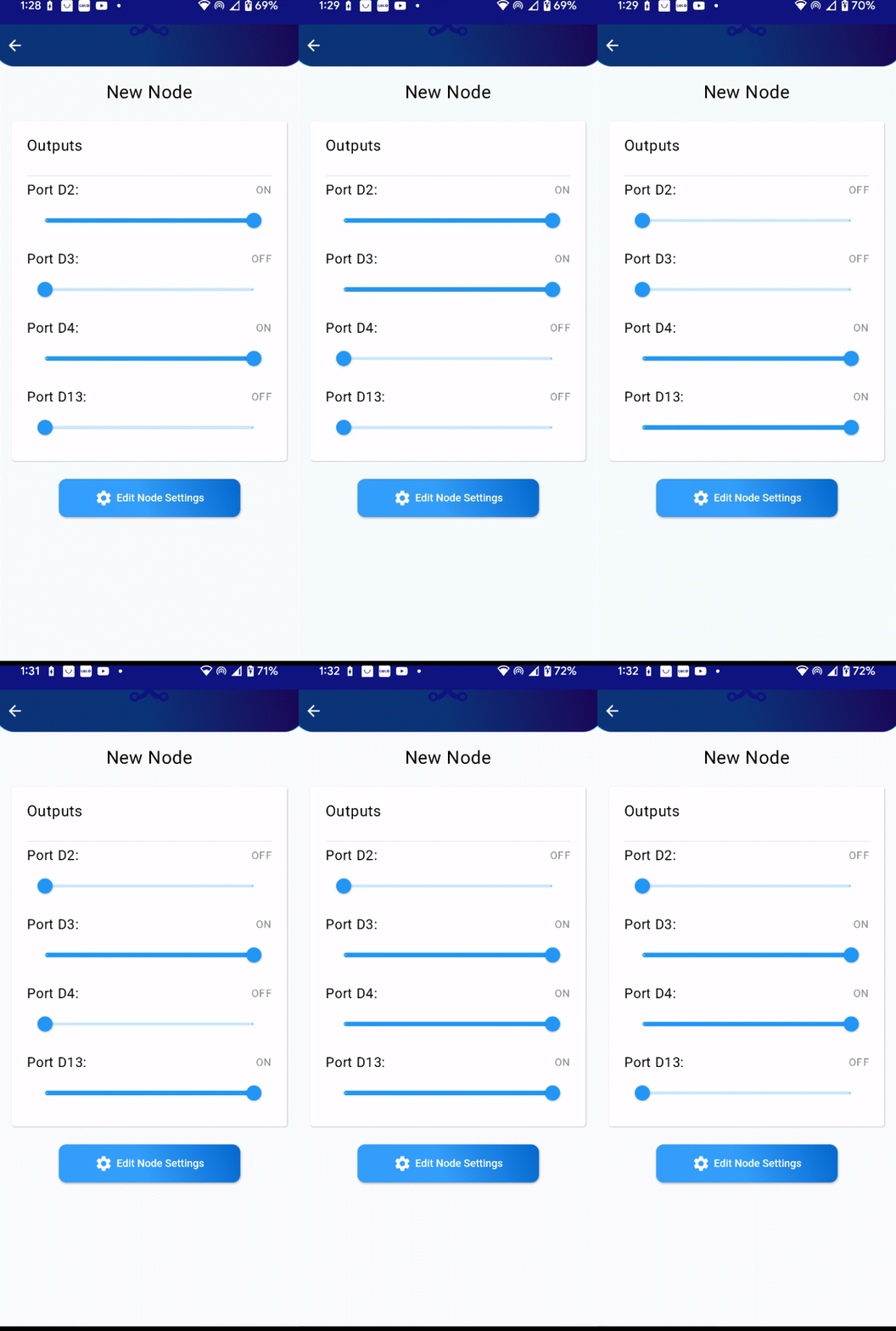
Test your system to ensure the ports are properly controlling the LEDs. Verify that the green, yellow, and red LEDs light up as expected.

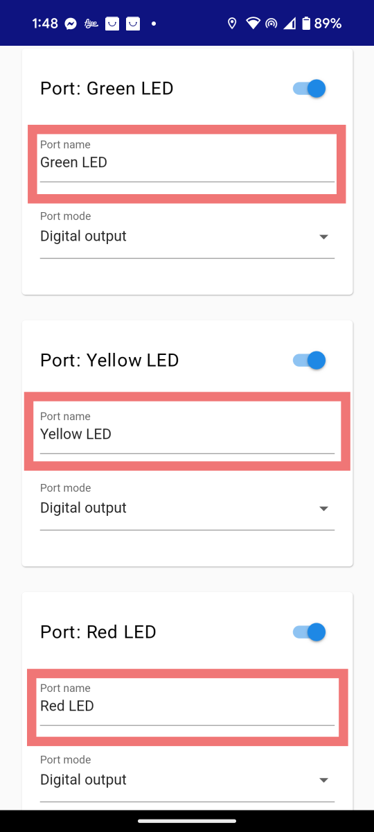
Step 7: Rename ports
Now we have 4 pins configured as output ports, it's better to name them according to their functions.
- Click on 'Edit Node Settings' button.
- for Each port used to connect LED, name it based on LED color that it controls.
- Click on the 'Save Settings' button at the end of this page.

Troubleshooting Tips
LED Not Lighting Up?
- Check if the LED is connected the right way (anode to positive, cathode to ground).
- Verify the resistor value (use a multimeter if available).
Loose Connections:
- Ensure all wires and components are securely placed in the breadboard.
Power Supply Issues:
- Confirm the power source is turned on and providing sufficient voltage.
Next Steps
In the following tutorial, we will explore how to control the brightnees of the LED with the Pulse Width Modulation (PWM) mode.
Disconnect your board but keep your circuit intact as you will need these connections in the next tutorial, where we will be controlling the LED brightness using Pulse Width Modulation (PWM). Make sure to double-check all connections to ensure they are secure and correctly placed, as this will help avoid any issues in the next steps.

