Configure LEDs Ports
This guide offers step-by-step instructions to configure three ports for Pulse Width Modulation (PWM) to control three LEDs: green, yellow, and red. Follow the steps below to complete the configuration process.
Step 1: Turn on your system
Turn on your board by plugging it into a power source using a USB cable or a DC adapter. Open your Tamra app and access your board from the app
- Sometimes you may need to wait a few seconds till your board and your Tamra app connect to cloud.
- Built-in LED flickers until the board connects to the Tamra Cloud.
- you can check the connection led in your app to make sure your Tamra app connects to the Tamra cloud.
- It's a best practice to restart Tamra application especially when it shows a black screen.

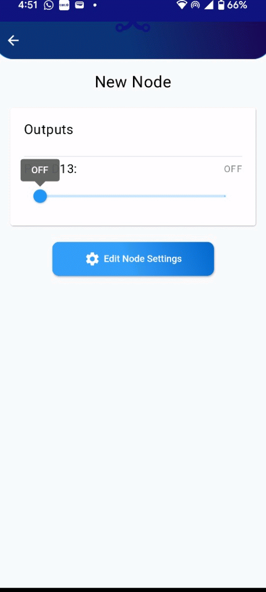
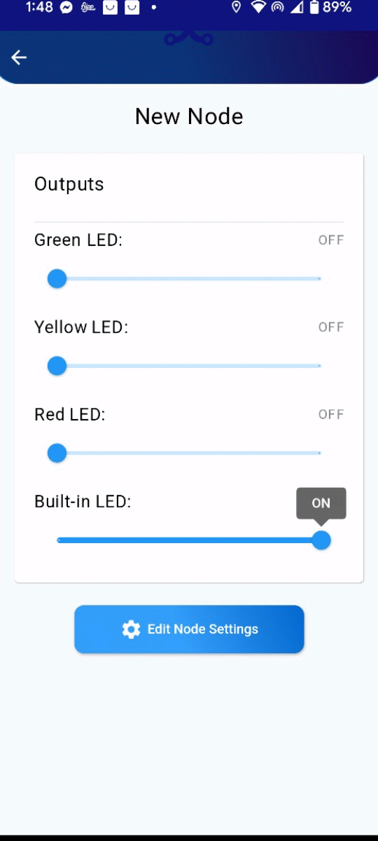
Step 1: Test the Built-in LED
Before proceeding, ensure the board is functioning correctly by testing the built-in LED. This step verifies that the board is operational and ready for further configuration.
Step 2: Access Board Settings
Always disconnect any circuit connected to Tamra board before changing the board settings to avoid damaging the board.
Click on the settings icon to access the board’s configuration menu. This step allows you to make necessary adjustments to the board’s ports.
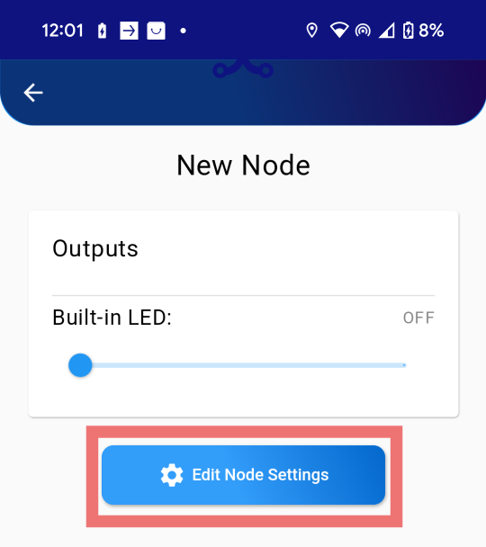
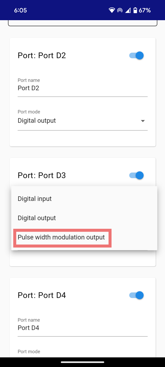
Step 3: Enable PWM Ports
Enable the ports needed for controlling the LEDs' brightness. Ensure that the correct ports are activated to avoid issues later in the configuration process.
Identifying PWM Configurable Ports
- The picture below highlights wave signs indicating ports can be defined as PWM output.
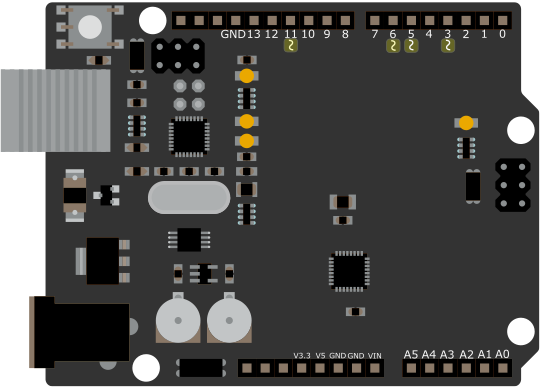
Ports 9 and 10 have the wave sign but cannot be configured as PWM outputs.
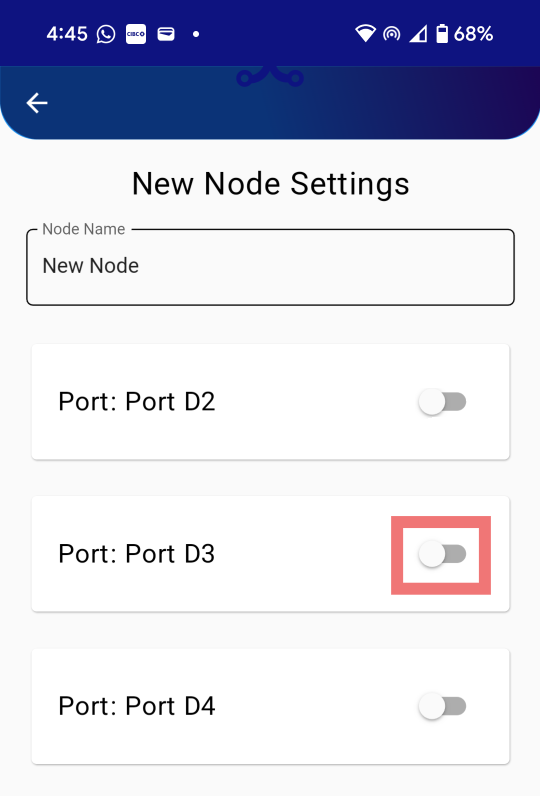
Step 4: Set Ports to PWM Mode
Set the ports to "Pulse Width Modulation Output" mode. This configuration ensures the ports can drive the LEDs and control their brightness effectively.
Ports of the Tamra board are reconfigurable. You can always reconfigure the pins based on your application needs. This flexibility allows you to adapt the board's functionality to different projects and requirements. When setting the ports to PWM mode, ensure that the selected ports support PWM functionality to avoid any configuration issues. Refer to the board's documentation for detailed information on port capabilities and limitations.
Step 5: Configure Three Ports
Enable and configure three ports as "Pulse Width Modulation Output". These ports will be used to control the green, yellow, and red LEDs.
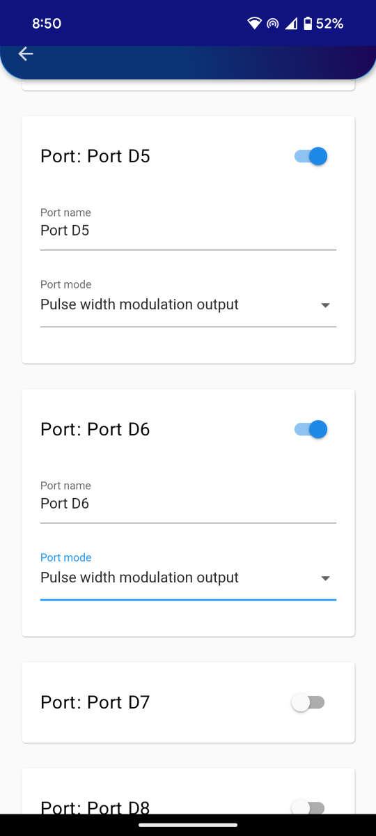
Always try to keep the built-in LED for testing the connection states of your board, your application, or your system generally. So, keep the configuration of port D13 as an output.
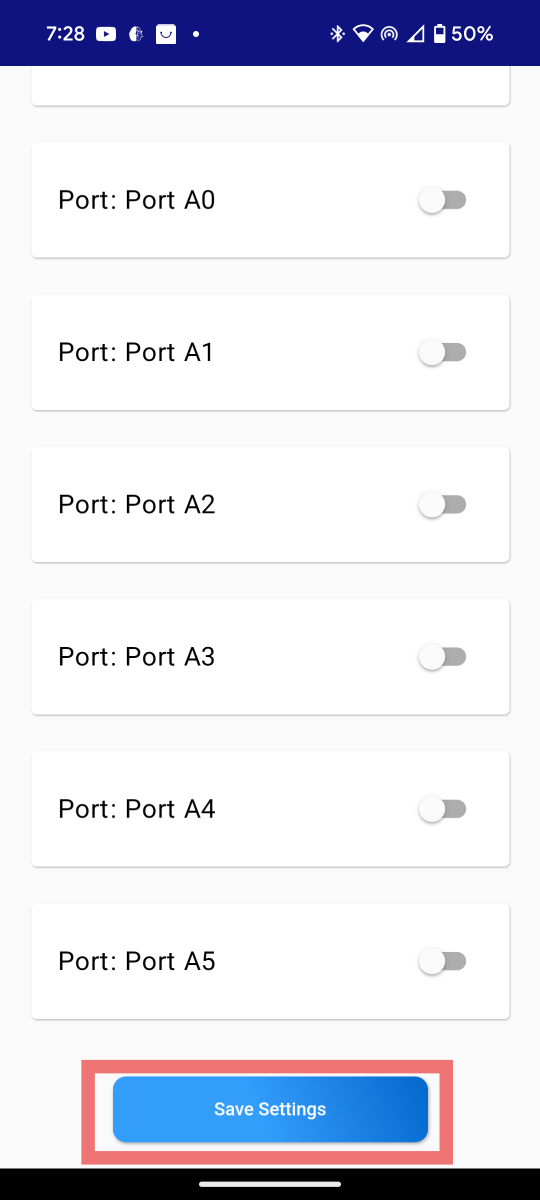
Step 6: Save Settings
Click on the 'Save Settings' button at the end of this page.
Step 7: Test Configuration
After configuration, test the board to ensure the port settings are properly configured. Verify that the Built-in LED lights up as expected.
Conclusion
By following these steps, you have successfully configured three ports as outputs to control the green, yellow, and red LEDs. If any issues arise, revisit the steps to ensure all configurations are set correctly.