
For this project, we are going to show you the steps you can take in order to build your own smart gardening system using the Tamra IoT platform. Our smart gardener is composed of two separate independent systems.
These features are:
1. Lighting System: The lighting feature enables you to control the light in the smart gardener on the Tamra application based on the value of the light intensity sent from the sensor to the application.
2. Watering System: With this feature, you can set the mode of your watering system to be automatic or manual. And for the manual mode, the feature enables you to open and close the pump when needed. It also shows you the value of the moisture sensor reading.
Components
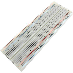
- Breadboard 630-Tie Point "BB-01"
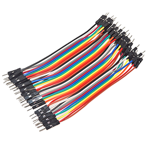
- Male-Male Jumper Connecting Wire
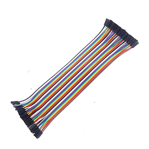
- Female-Female Jumper Connecting Wire
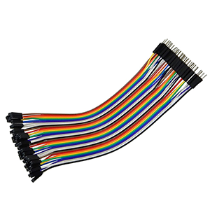
- Male-Female Jumper Connecting Wire
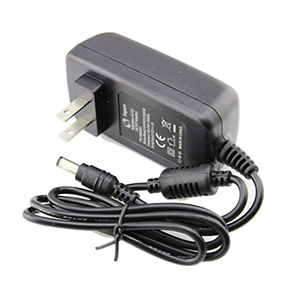
- Wall Adapter Fixed 12V 2A DC
- Wall Adapter Fixed 5V 2A DC
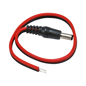
- 2x DC 2.1mm Female Plug 25cm
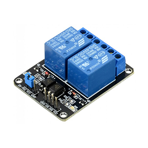
- 5v Dual Channel Relay Module with Optocoupler
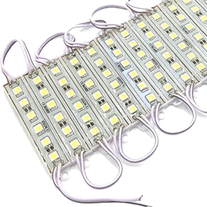
- LED Strip 12V
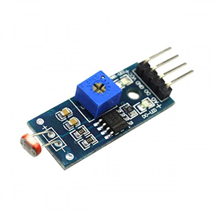
- LDR 4-Pin Photosensitive Resistor Sensor
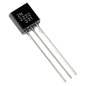
- Transistor 2N2222 "NPN"
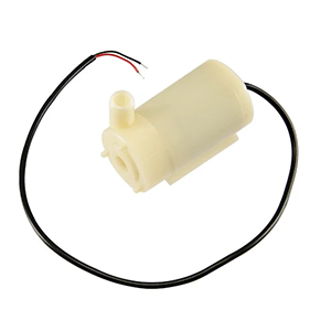
- Water Pump Mini DC 3-6V 120L/H
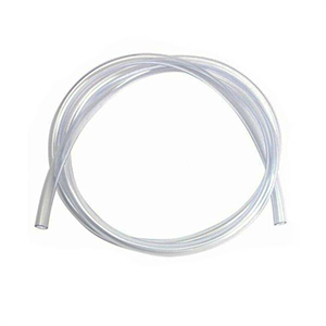
- Water Pump - Hose 6x8mm - PVC Clear Vinyl Tubing
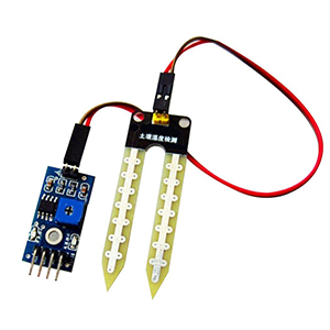
- Soil Moisture Sensor
- Insulating tape
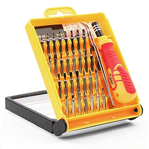
- Screwdriver

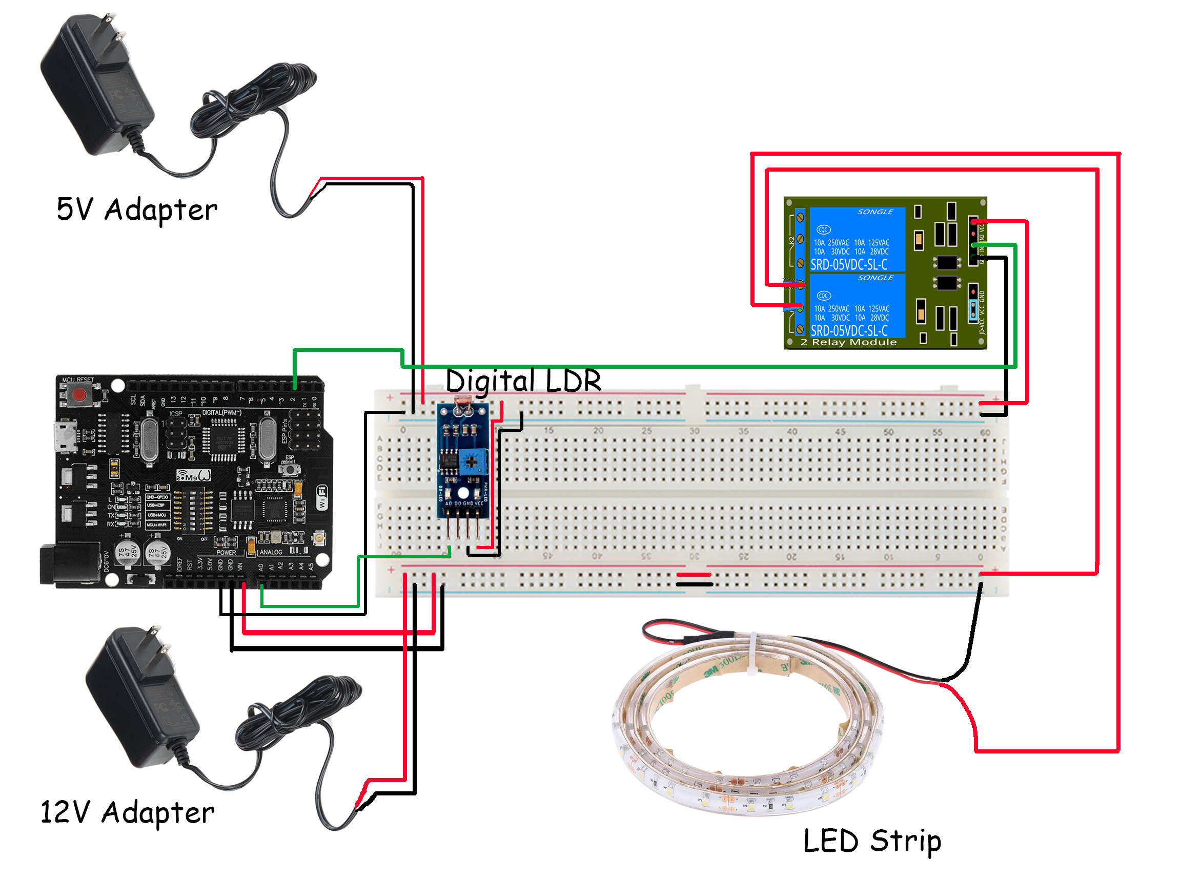
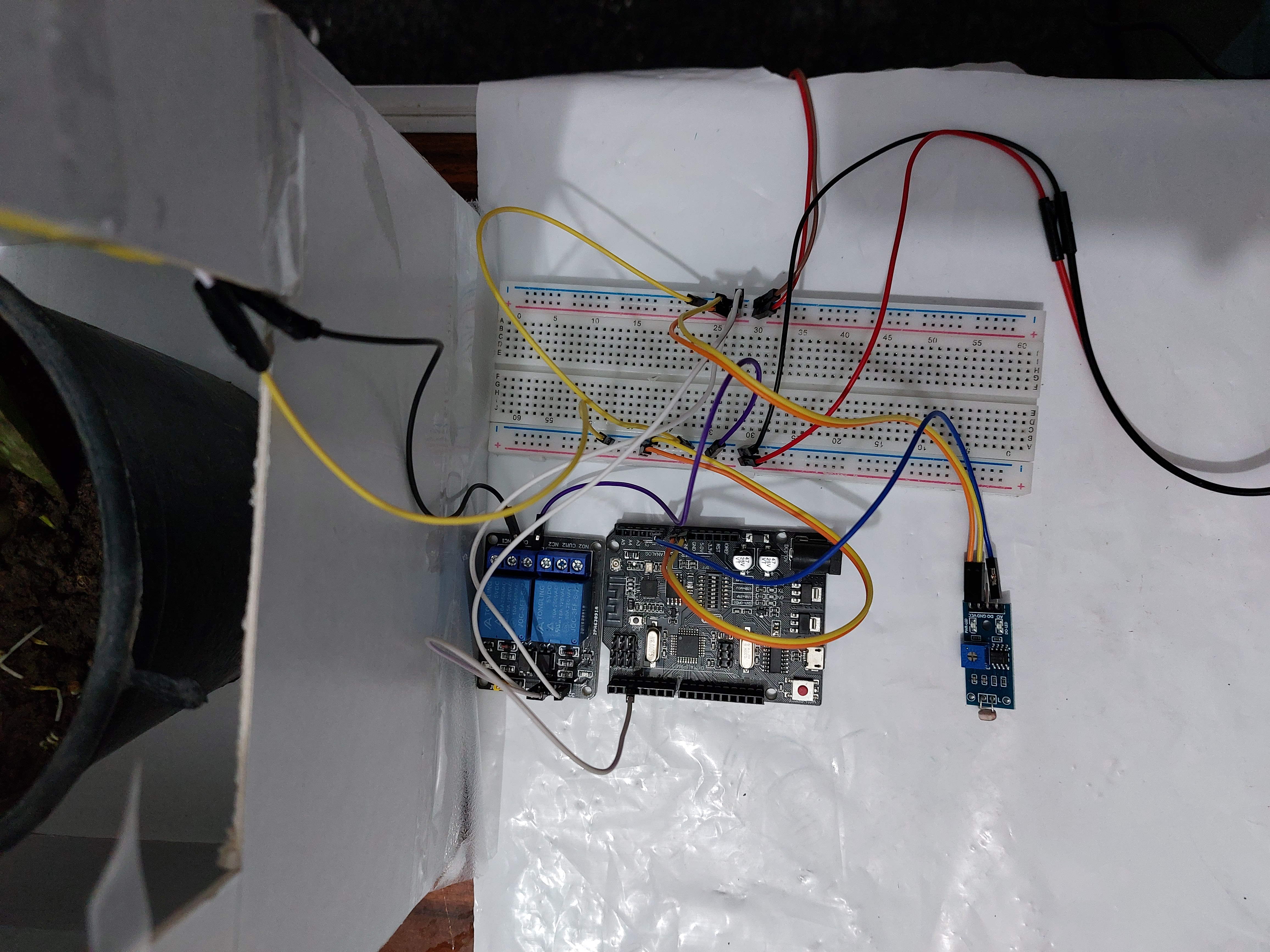
Step 1: powering up your system
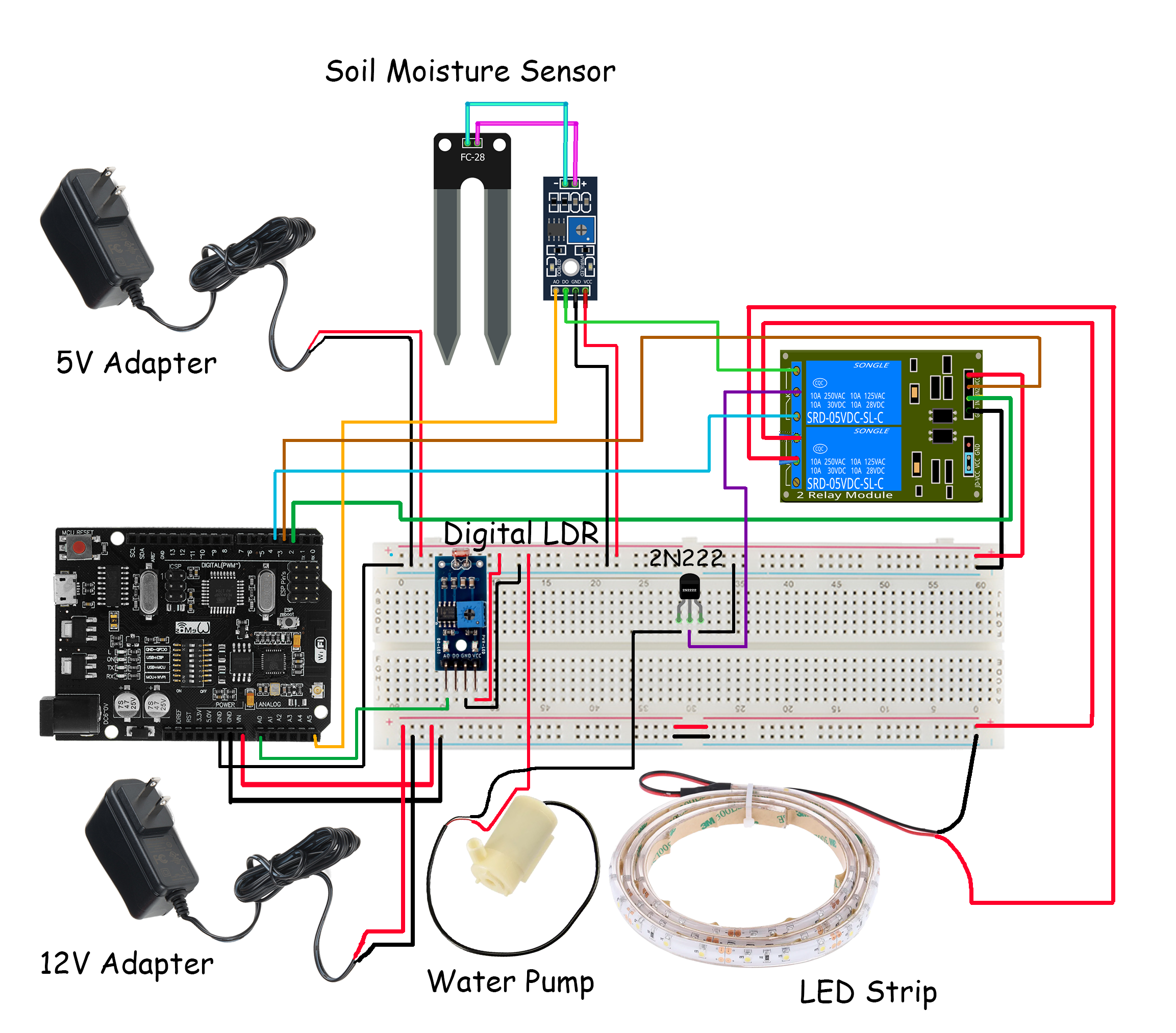
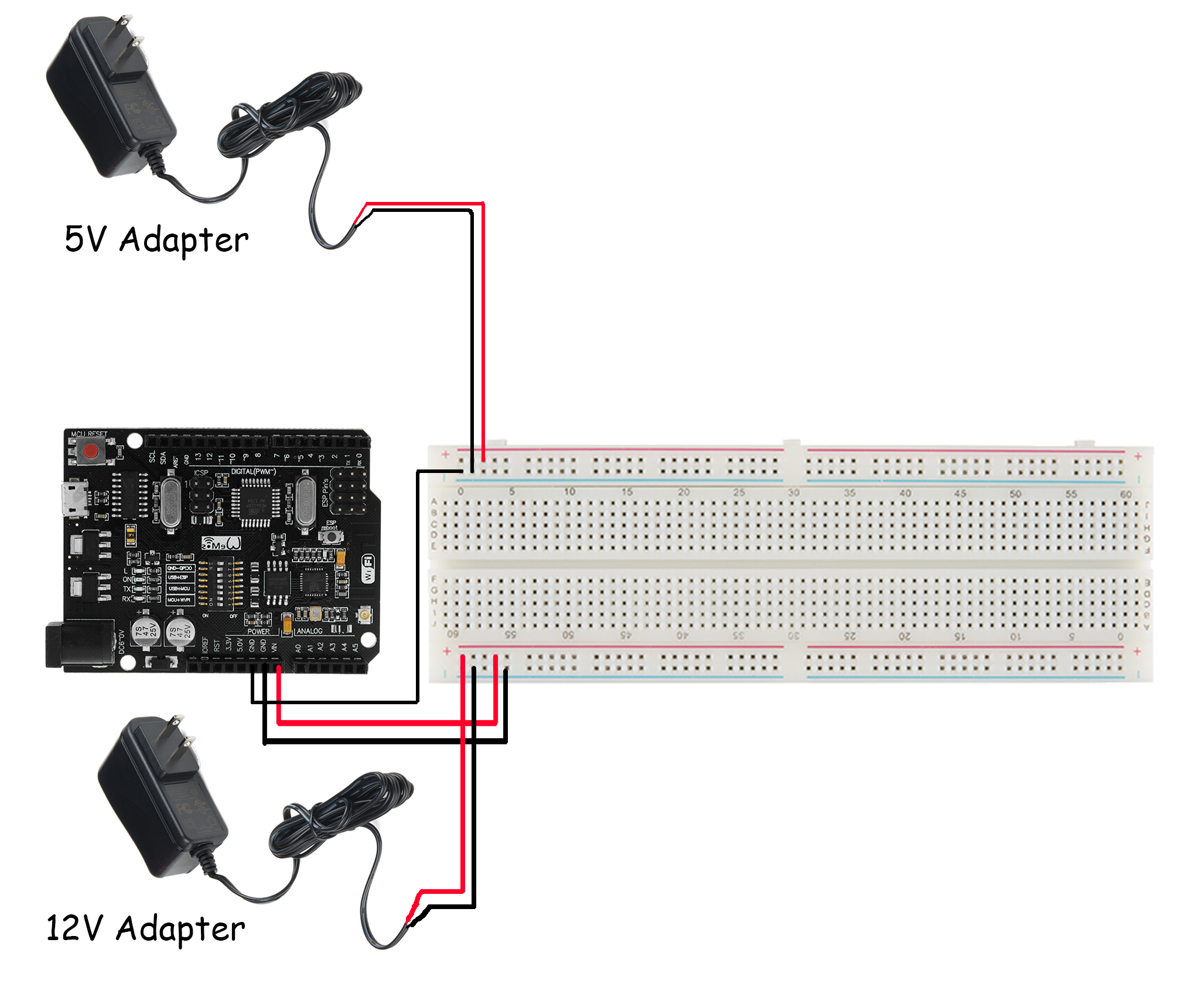
The first and most vital step is to connect the power sources to your breadboard. This can be achieved by following the next steps closely.
- You'll want to connect the 12V adapter to the female plug as shown in the picture.
- We'll strip two jumpers with male ends from the other end. This male end will be inserted in the breadboard as shown in the picture, with the red VCC wire in the +ve line and the black GND wire in the -ve line. The other stripped side will be attached to the female plug as shown in the picture. Make sure to secure the connection by twisting the bare wires together and applying tape to the stripped parts.
- After, we'll want to repeat the same steps with the 5V adapter. We'll connect to the female plug, and then we'll strip to jumpers and connect the 5V adapter to the breadboard on the other power line: GND to -ve line and VCC to +ve line.
- After making sure the connection is secured using insulating tape, we'll use a male-male jumper to connect the two -ve lines on both power lines (common GND).
- The first thing we'll start to power up will be our Tamra board. We'll do this by using a male-male jumper to apply 12V from the VCC line we just powered up to the Vin pin of our board. We'll use another male-male jumper to connect a GND pin to any GND line on the breadboard.
Now that we have our power options ready and our Tamra board powered up, we'll start implementing our features at a time!
You can use any 12V and 5V DC power supply available and follow the same steps of using jumpers to connect the VCC and GND wires to the +ve and -ve lines on your breadboard respectively.
Step 2: lighting control in your smart gardener
What we want to accomplish here is to be able to turn the LED strip on and off from our Tamra application. We'll also implement a light intensity sensor to monitor the light the plant is subjected to. The steps to forming our lighting system are as follows:
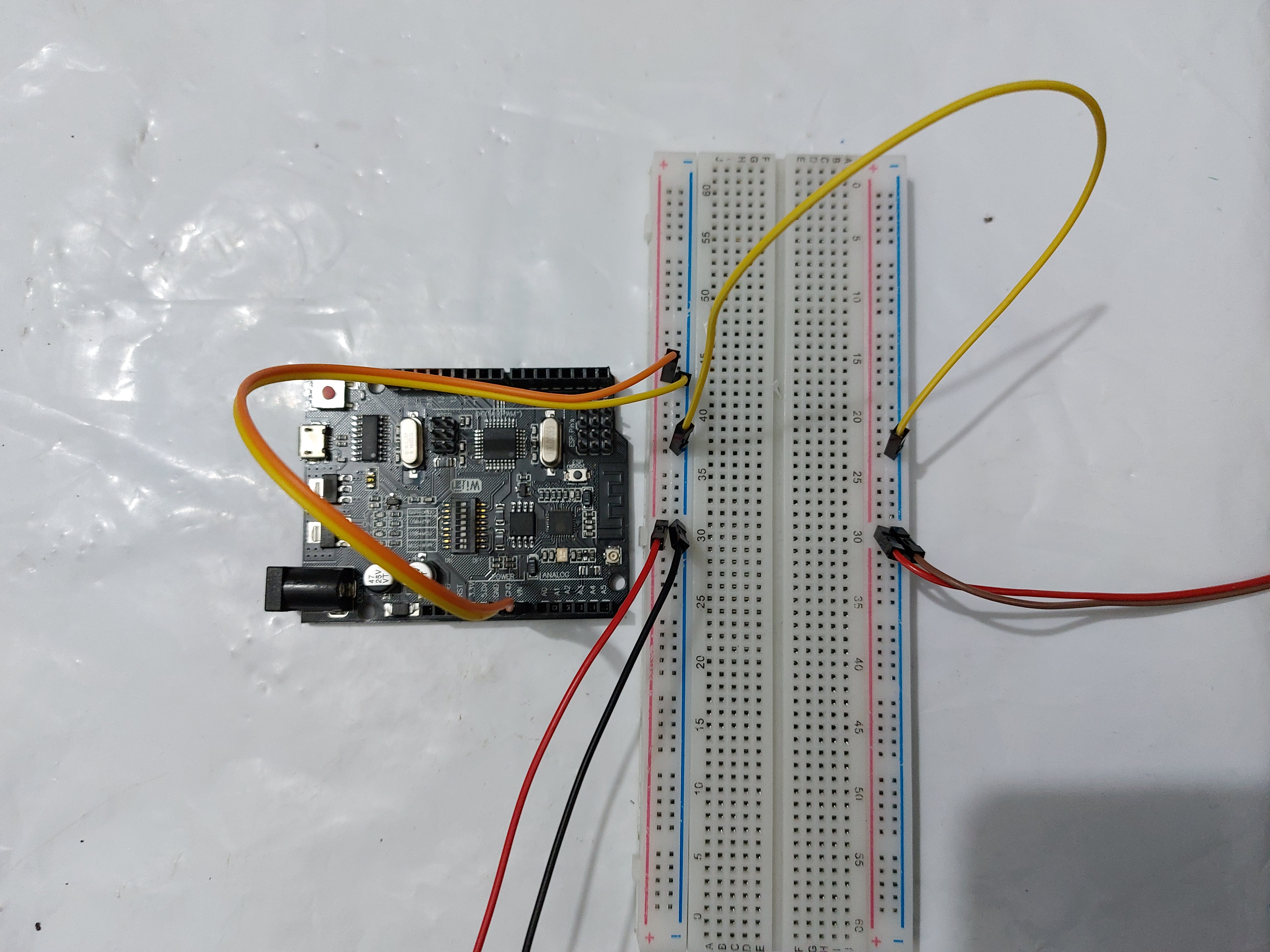
- We'll start by connecting our LDR sensor. You'll notice the sensor has 4 pins: (left to right) A0, D0, GND, and VCC. We'll power it up by connecting a female-male jumper between the VCC pin and the +ve 5V line, and another female-male jumper between the GND pin and any GND line. For the reading of the sensor, we'll connect a female-male jumper between the A0 pin on the sensor and the A0 pin on the Tamra board. That way, we'll receive the analogue value of the light intensity inside our smart gardening system.
- Power your relay module up by using female-male jumpers to connect the VCC and GND pins on the module to the 5V and GND lines on your breadboard.
- We'll strip two jumpers with male ends from the other end. The stripped sides will be attached to the two wires on one end of the LED strip as shown in the picture. This step is to make handling the LED strip easier than working with wires. Make sure to secure the connection by twisting the bare wires together and applying tape to the stripped parts.
- Now that we have male ends to the LED strip that are easier to work with. We'll connect the GND jumper of the LED strip to any GND line on our breadboard. After, we'll connect the male end of the VCC jumper of the LED strip to the relay's COM1 as shown in the picture.
- We'll connect the NO1 pin on the relay to the 12V line on our breadboard with a male-male jumper.
- Finally, for the IN1 pin, we'll connect it to any digital pin on our board using a female-male jumper. We chose pin 2 for this step.
This system is adjustable to your plant so that when the light intensity is above a certain value on your application, you can turn your LED strip on to control the light the plant is subjected to.
If the relay you're using is Active Low, the operation of the ON and OFF slider in your application is reversed, i.e., when you press OFF the LED strip turns on and vice versa.
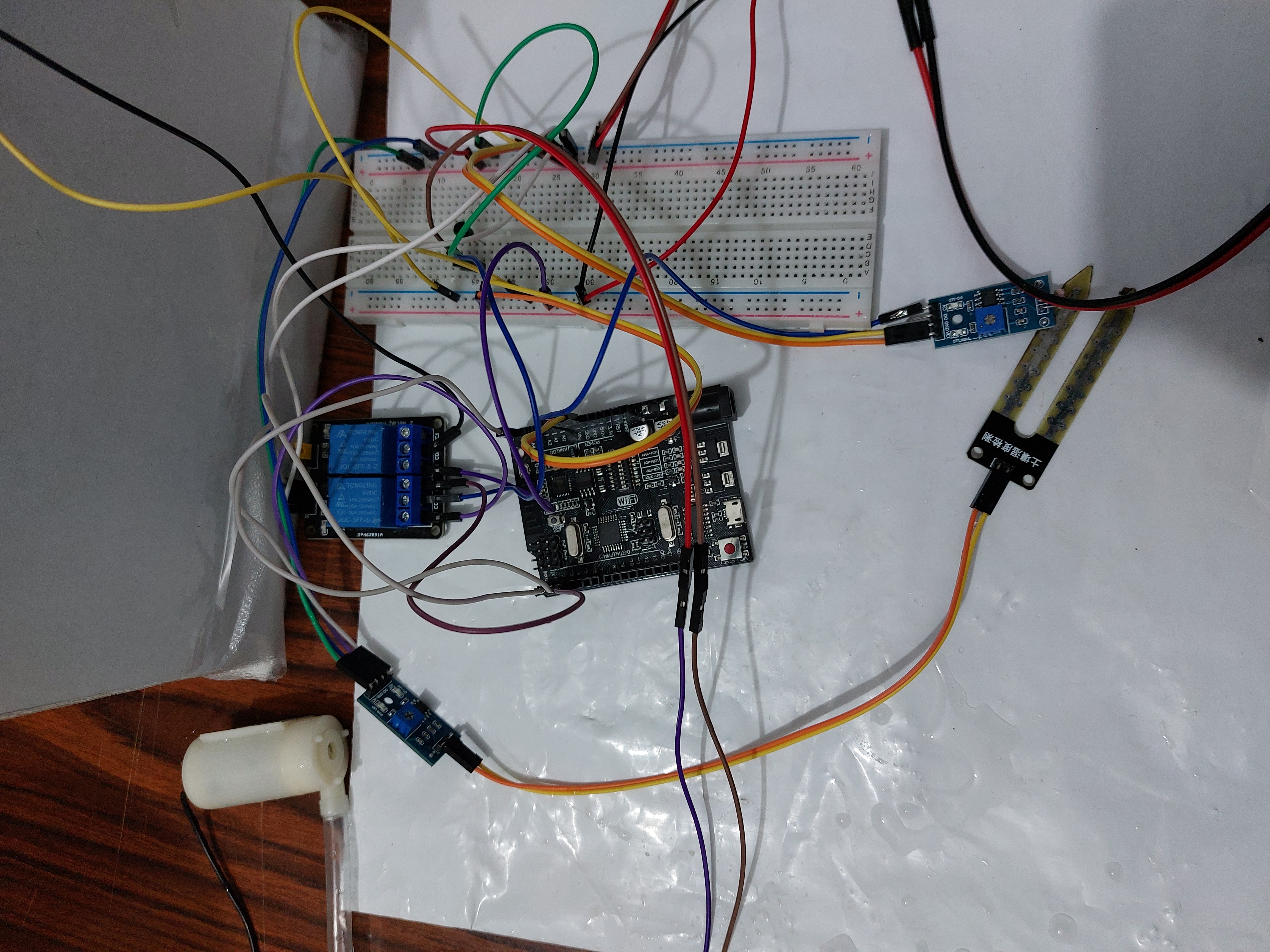
Step 3: watering control in your smart gardener
For this feature, we'll use the application to set the mode of our water pump to work either automatically or manually. We'll also be able to view the moisture content value on the Tamra application as well as manually open and close the pump. When the pump mode is automatic, the pump is turned on when the value of the moisture content in the soil is greater than a certain value. This value can be adjusted by changing the sensitivity on the sensor. To implement this system, we'll go through the following steps:
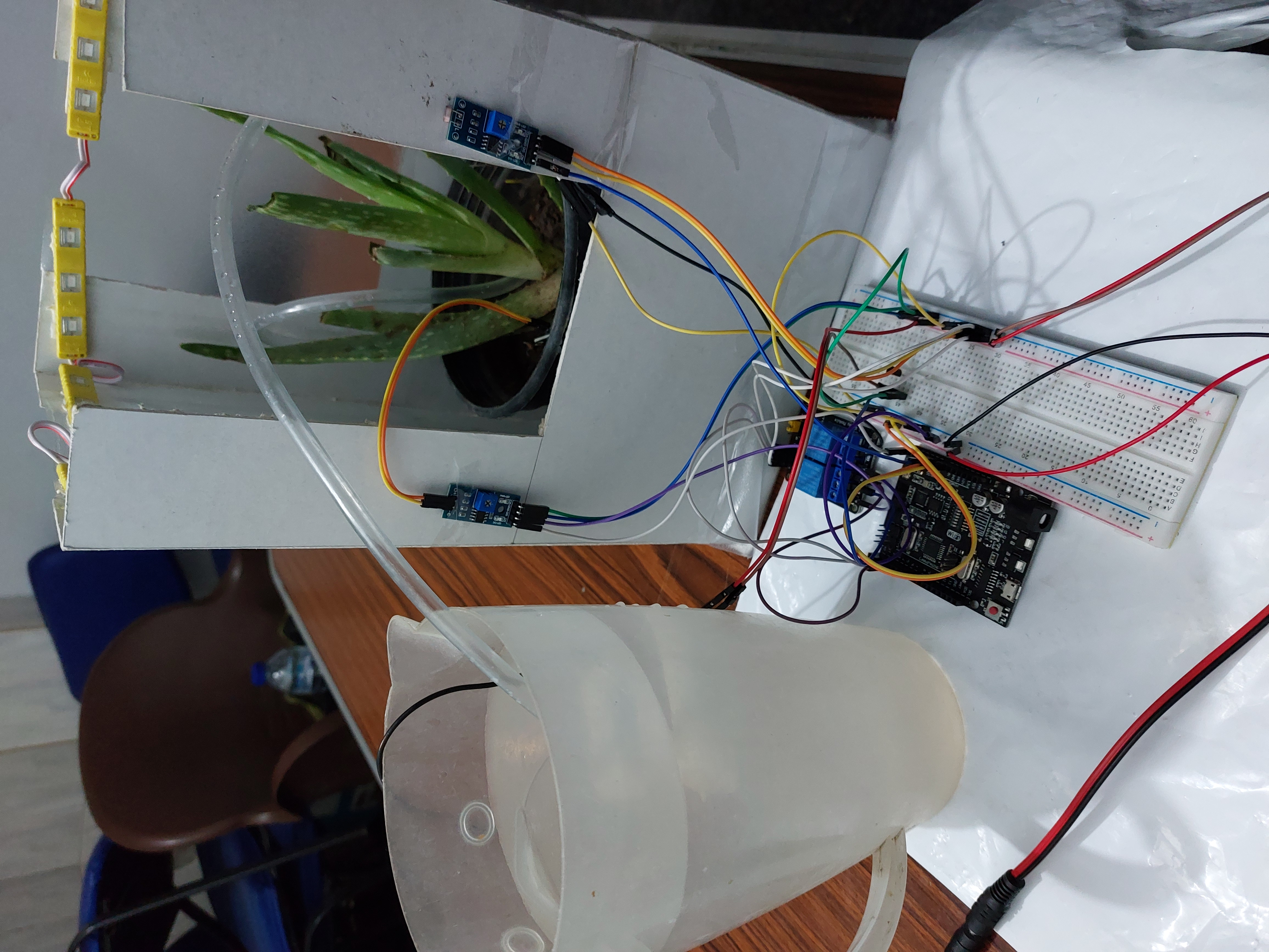
- At the beginning of this set of steps, we'll connect the two pieces of our moisture sensor together as shown in the picture below. We'll also attach our transistor to our breadboard so we can start with our connections.
- We'll strip two jumpers with female ends from the other end. The stripped sides will be attached to the two wires on one end of the pump as shown in the picture. This step is to make handling the pump easier than working with wires. Make sure to secure the connection by twisting the bare wires together and applying tape to the stripped parts.
- If you inspect your moisture sensor, you'll find that it has 4 pins (legs): (left to right) A0, D0, GND, and VCC. We'll connect the pin named GND to any GND on our breadboard with a female-male jumper. For the VCC pin, we'll connect it to the +ve 5V line on the breadboard with another female-male jumper. We'll connect the A0 pin on the sensor to the A5 pin on the Tamra board with a female-male jumper. For the D0 pin, we'll use a female-male jumper to connect it to the NO2 of the relay.
- After connecting the NO2 of the relay, we'll use a male-male jumper to connect the NC2 to a digital pin on the Tamra board. For this step, we've chosen pin 4. We'll also connect the IN2 to another digital pin on the Tamra board using a female-male jumper, like pin 3. This is the pin we'll use to select the mode of the system: manual or automatic. For the COM2 of the relay, we'll use a male-male jumper to connect it to the base of the transistor.
- For the rest of the legs on the transistor, since we've established that its base is connected to COM2 of the relay. Now, we'll connect its collector pin to any GND pin on our breadboard using a male-male jumper. Its emitter will be connected to the GND of the pump using another male-male jumper.
- We'll use a male-male jumper to connect the VCC of the pump with a pin on the +ve 5v line.
This system is also adjustable to your plant so that when the moisture content in soil is above a certain value on your application, you can turn your pump on to control the water content the plant is subjected to.
The sensor's reading is analogue which means we'll set our port mode to Analogue Input.
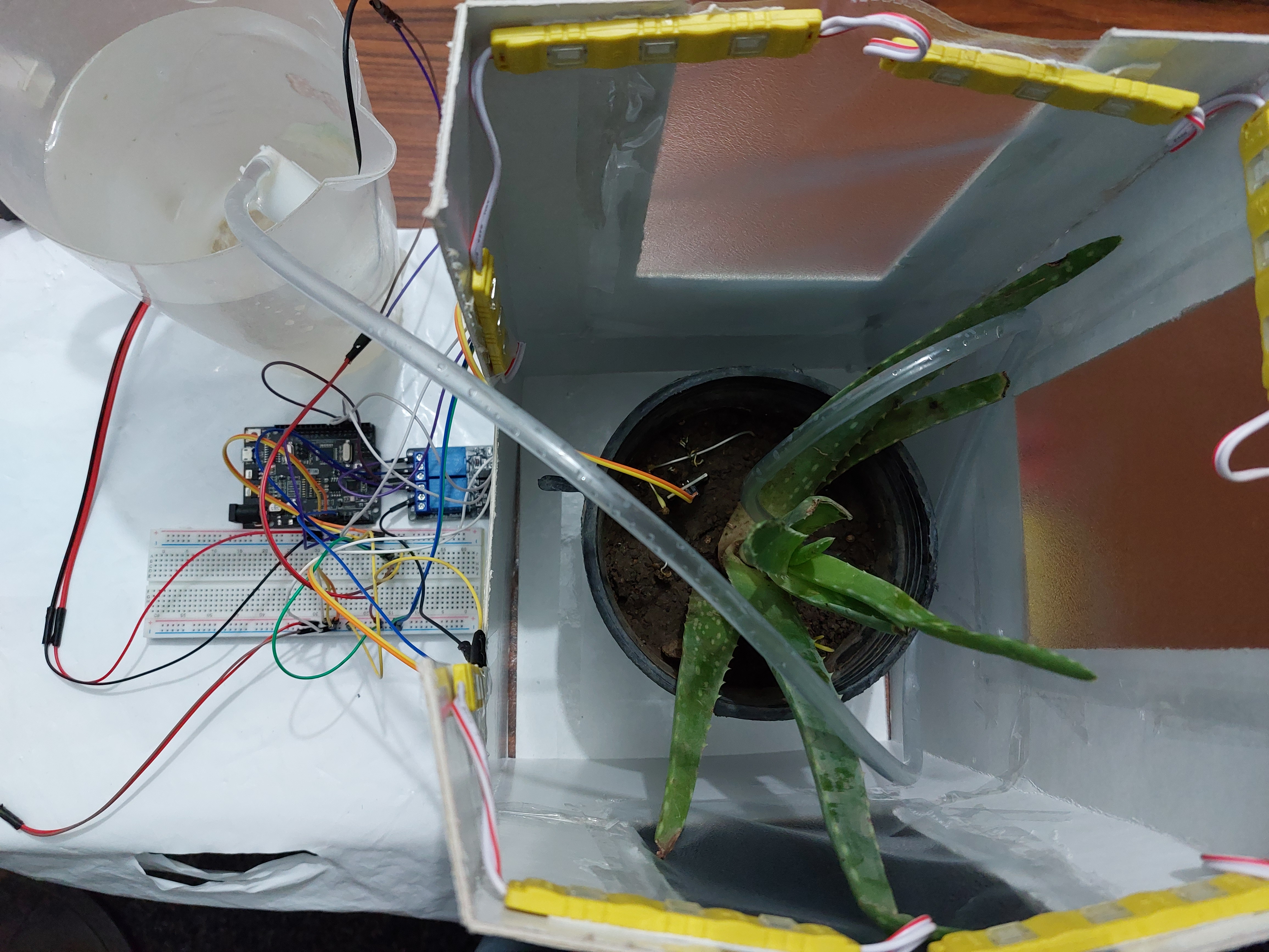
Step 4: testing our smart gardener
Now that all our connections are ready, it's time to power our smart gardening system up and give it a try.
If you don't have a tamra account at this point, you should probably Create An Account to be able to keep going.
After inserting both adapters in your 220V outlet, you'll notice that Tamra's wifi appeared in your available wifi connections. On connecting to the Tamra IoT wifi, it should automatically open a window for you to enter your wifi credentials and the activation code necessary to activate your node. You can find this activation code when you open your Tamra application. Now, we'll now hop onto the application to try the project out.
The first thing we need to do is configure our node to our system by going through the following steps:
- We'll click on the burger menu at the upper left corner of the screen.
- Click on Connected Nodes.
- Press the Settings icon next to the New Node.
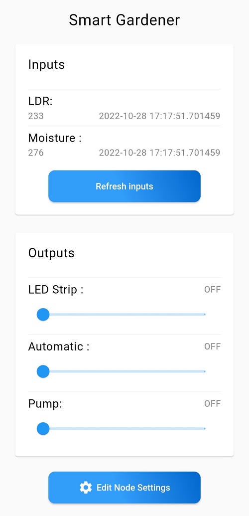
- Press on the Node Name box to change its name to the project name: Smart Gardener.
- Swipe the switches next to our used pins to activate their equivalent ports, change their names, and set their port modes according to the following list:
- Port D2: LED Strip, Mode: Digital Output
- Port D3: Watering System Mode, Mode: Digital Output
- Port D4: Manual Pump Control, Mode: Digital Output
- Port A0: Light Intensity Sensor, Mode: Analogue Input
- Port A5: Soil Moisture Sensor, Mode: Analogue Input
Make sure to save your new settings from the Save Settings button at the end of the page.
If you're not sure which port mode to use, are confused about why we choose each mode, or don't know how to select the mode you want, you can find answers in Editing Port Settings.