Explore your hardware
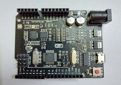
The board in the picture below is designed by Robotdyn company. For simplicity, the founders named this board Tamar board since it is produced by several companies and does not have a recognizable name. Tamra Board is a customized version of the classic ARDUINO UNO R3 board. Full integration of microcontroller Atmel ATmega328 and IC Wi-Fi ESP8266 with 32 MB flash memory, and USB-TTL converter CH340G on one board.
The Tamra board you're currently holding in your hands provides you with endless possibilities. You can only make the best of an opportunity when you understand it well, and the first step to understanding your board is getting familiar with the hardware itself. Looking at the board, you can see power inputs, a bunch of electronics, and pins! So let's get to know it piece by piece.
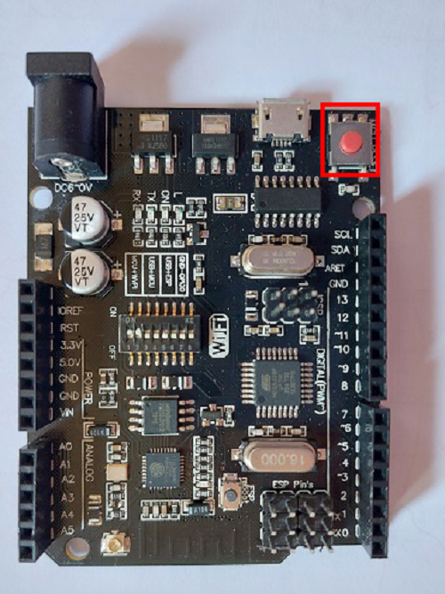
Reset button
The reset button is the red button on the corner of your board. This button doesn't delete the code uploaded on the board, but restarts the application or process it does. For example, if you have a program that counts from one to ten and displays the number on a screen, pressing the red reset button when the number seven is displayed would restart the counting process from one again! Think of it as the restart button on your PC.
Power inputs
There are 3 Power Inputs to your board:
- The Black Power Jack
- The USB Cable Port
- The Vin Pin
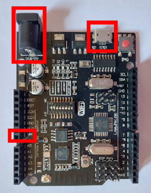
You can read all about these three components and how to use them in Powering up section.
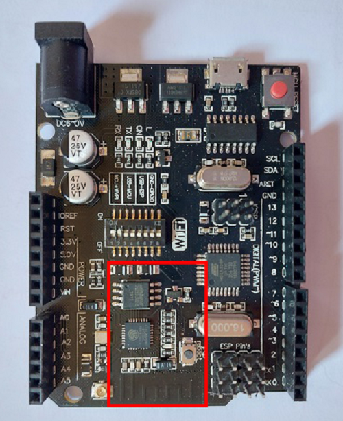
Microcontroller
It's the brain of the board. It performs all the necessary operations from receiving the inputs to applying procedures on them, and eventually to giving you final results. The microcontroller on your board is ATmega328P.
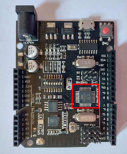
Wifi module
The wifi module is what allows the board to connect to the wifi. The wifi module in your board is ESP8266.
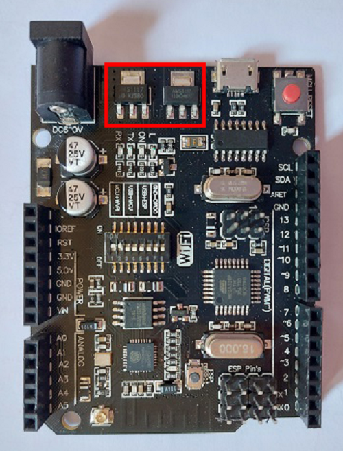
Voltage regulators
What you need to know about the regulators embedded on your board is that their purpose is to regulate the voltage input to the board, to prevent its damage and overheating. They convert the input voltage from (7-12V) to 5V and 3.3V.
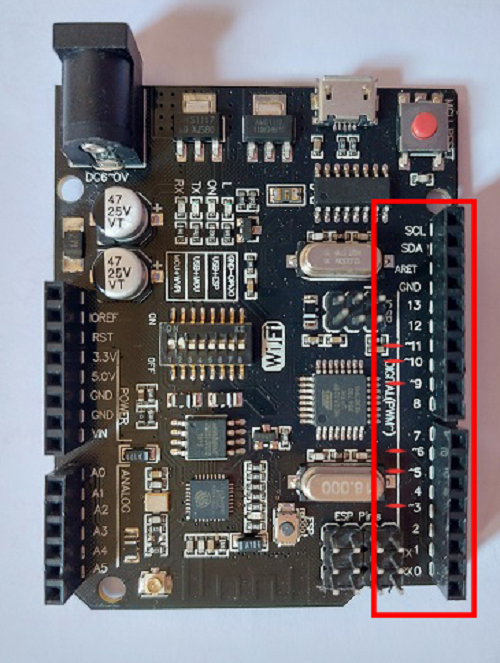
Pin layout
The pins are what connects your board to the outside world. This includes both input devices and output devices. If you're unfamiliar with inputs and outputs, check Input vs output.
The pins are classified into Digital and Analogue pins, to learn more about digital and analogue signals, check Digital vs analogue.
The pins on the board are divided into:
- Power Pins
- Analogue Input Pins
- Digital Input/Output and PWM Pins
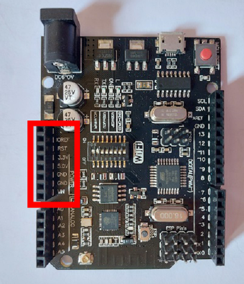
Power pins
The pins shown in picture are called the Power Pins of the board. The most important pins will be briefly discussed below.
- Vin Pin : One of the powering up methods that can be used to start your board. It's well-explained in the Powering up section.
- GND Pins : Ground Pins.
- Power Pins : Provide VCC output from the board to other components. They're divided into two pins: 3.3V and 5V.
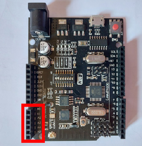
Analogue input pins
Analogue input pins are 6 distinct pins named A0-A5. They're used to take analogue inputs from input devices to the board. For example, if we want to make a small project to measure temperature and print it on a screen. Since temperature is considered an analogue value that can be any number (ie: 5C, 38C, 120C, etc), then a temperature sensor is considered an analogue input to our board. It will measure the surrounding temperature and send that value to the board. This temperature sensor will be connected on one of these analogue input pins.
Digital input/output and PWM pins
These multi-purpose pins can be both digital inputs and outputs. Meaning that, for example, if we want to make a simple project where pressing on a push button turns an LED on for 3 seconds, we'll connect both the push button and the LED on any of the pins shown in the picture.
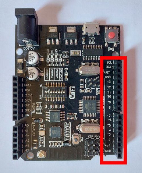
Not only that, they're also used with analogue outputs. Analogue outputs or PWM Pins are indicated by a small wave sign (~) next to them. These pins can also be used as normal digital input/output pins.
For more information on what PWM is, visit the Signal types page!