Digital vs analogue
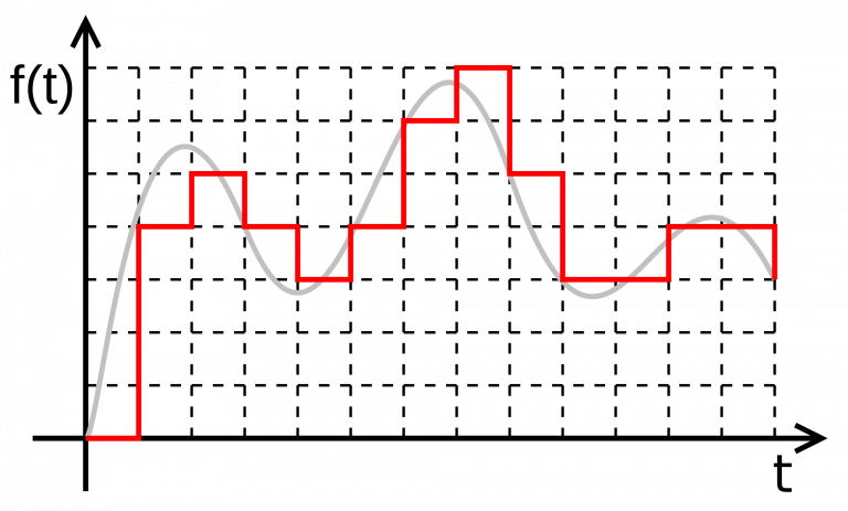
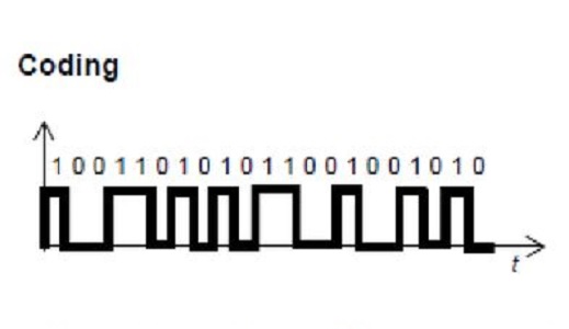
The nature of all signals is categorized into two categories: Digital and Analogue. These signals can be light waves that are emitted from a light source, which are analogue signals, or signals a push button sends the microcontroller when it's pressed, which is an example of digital signals. The graph shown below is for an analog signal and its digital version. Computer systems, like your PC or microcontrollers, deal internally with digital signals ONLY, so analog to digital converters can prepare the signals for these devices.
Identifying the nature of the signal you're using in your application is important. This way, you can adjust your microcontroller so that it understands the signal it's dealing with and gives you the options to manipulate and control it accordingly.
Digital signals
Digital signals are not continuous, but are discrete in value and time. These signals are represented by binary numbers and consist of different voltage values.
In a simpler manner, digital signals are used to represent any definite variable, a variable that is either yes or no. For example, take a look at your light switch. The light switch is either turned on or turned off. The same can be said of digital devices, they send/receive signals that are either 1 or 0 (1 representing 5V of electricity transmitted, and 0 representing 0V transmitted).
An LED can be considered a digital output if it's programmed to turn on when someone goes through the door.
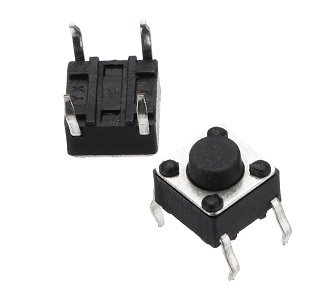
Digital input examples:
- Push Button
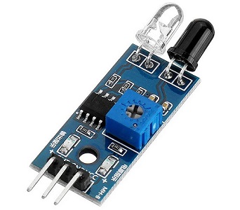
- IR Sensor
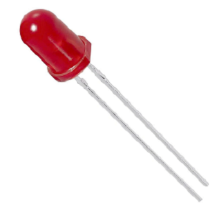
Digital output examples:
- LED
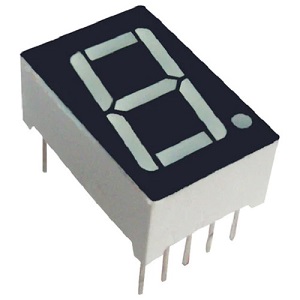
- 7 Segment
Analogue signals
These signals are continuous in both values and time. They can be used to represent all the signals in between 0 and 1 (ie: 1V, 2.5V, 4V, etc).
For exapmle, the same LED we could turn on digitally, we could also program and control its light intensity according to other parameters.
Analogue input examples:
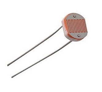
- Light Intensity Sensor
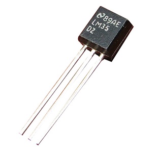
- LM35 Temperature Sensor
Analogue output examples:
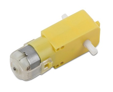
- DC Motor
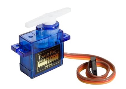
- Servo Motor
PWM
Analogue outputs are a tricky concept. You can't actually just put analogue outputs directly into the world. Instead, you push it out step by step. This is done using the PWM concept.
PWM stands for Pulse Width Modulation. It is a technique used in controlling the brightness of LED, speed control of DC motor, controlling a servo motor or where you have to get analogue output with digital means.
Digital pins either give us 5V (when turned HIGH) or 0V (when turned LOW) and the output is a square wave signal. So if we want to dim an LED, we cannot get the voltage between 0 and 5V from the digital pin. So, instead, we use PWM.
PWM is when we change the ON and OFF time of the signal. First, let's dissect the square signal.
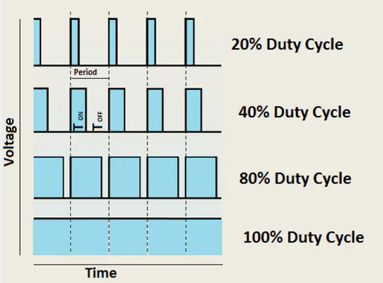
The square signal has:
- TON: On time, the time where the signal is HIGH.
- TOFF: Off time, the time where the signal is LOW.
- Period T: the sum of on time and off time.
- Duty Cycle: the percentage of Period T where the signal is HIGH (TON/T).
So a 50% duty cycle means that the square wave will be HIGH for half the time of the signal and LOW for the other half.
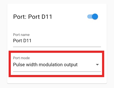
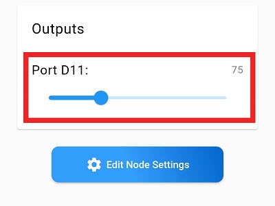
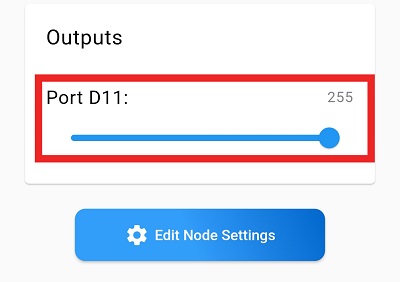
Choosing the PWM Output option on the Tamra application as shown in the picture allows you to send a value between 0 and 255 on the output, which means that it sends voltage between 0 and 5V.
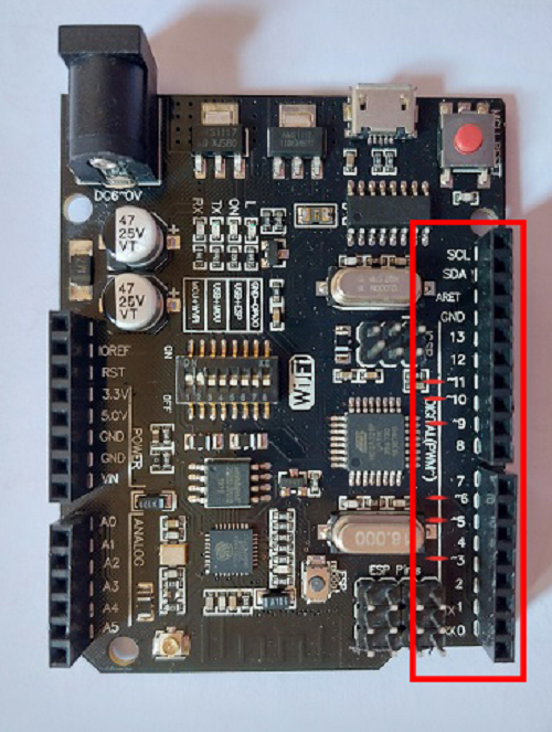
On the Tamra board, the pins with the wave sign (~) next to them are PWM specialized pins. They can still be used as normal digital input or output pins.
ADC
As we know, the microcontroller is a small computer, which means it only understand 0 and 1. So, for the microcontroller to read analogue inputs. it needs ADC.
ADC stands for Analogue to Digital Converter. It's a feature in our board that converts analogue voltage on a pin to a digital value, so it's considered the opposite of the PWM which convers a digital value into an analogue value. Since all the natural waves in the universe are analogue, the ADC is important so that the microcontroller can interface with the world.
This process is divided into three stages:
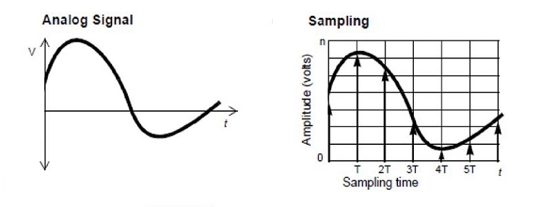
1.Sampling
Sampling is a process of measuring the amplitude of a continuous-time signal at discrete instants, converting the continuous signal into a discrete signal.
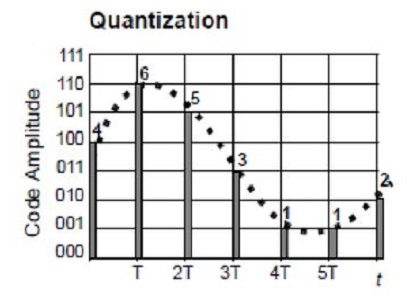
2.Quantization
The result of sampling is a series of pulses with amplitude that can be infinite with non-integral values between two limits. Quantanization is to limit these values into finite number of levels by tounding the sample value to the nearest level value.
3.Encoding
In combining the process of sampling and quantization, the specification of the continuous-time analog signal becomes limited to a discrete set of values.
Representing each of this discrete set of values as a code called encoding process.
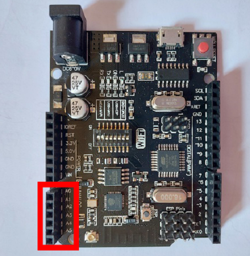
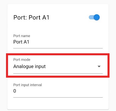
On the Tamra board, the Analogue Input Pins contain a built-in ADC that converts the signals it receives from analogue to be processed by the processor in the digital form. The ADC is on our A0:A5 pins. So, if you want to connect an analogue input device, you should connect it to one of these pins.
Also the reading coming from these pins are between 0:1023, which means that when you read 0 then it's 0V, when you read 1023 then the voltage applied is 5V, when you read 511, it's 2.5V, and so on.
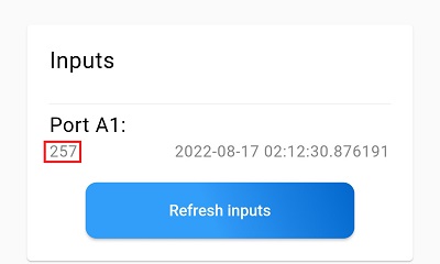
To sum it up, the voltage applied to the analogue pin (which is between 0V and 5V) is mapped into a value between 0:1023 that is shown in your application.